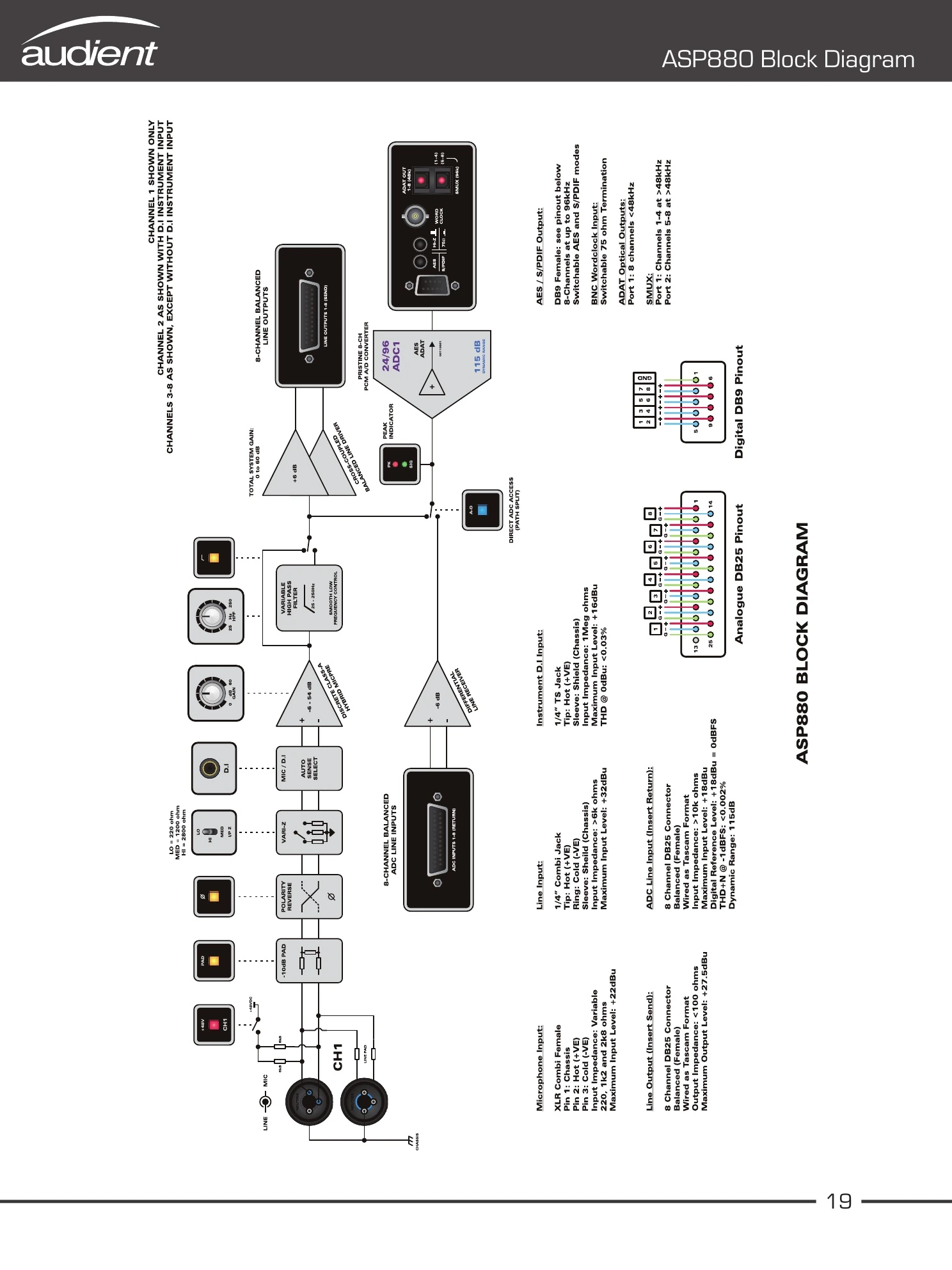
Block Diagram
The source-manual diagram shows the complete signal flow. Channels 1 and 2 include the instrument input and −10 dB pad. All channels include polarity reverse, variable impedance, variable high-pass filtering, an analogue line output / insert send and direct ADC access / insert return.
The built-in ADC feeds simultaneous AES/S/PDIF and ADAT SMUX outputs. The diagram also contains the analogue DB25 and digital DB9 pinouts.