Patchbay
The patchbay
The ASP8024PB optional patchbay system provides front-panel access to connections provided on the rear of the standard console, as well as additional patch points. Patching is implemented using TT-size jacks with D-sub connectors for studio-system interfaces.
All default signal paths are fully normalled to avoid unnecessary patching, and functional patch-point blocks are arranged horizontally for identification. Interfacing for two 24-track machines is provided and the patchbay is supplied with 144 tie-lines as standard.
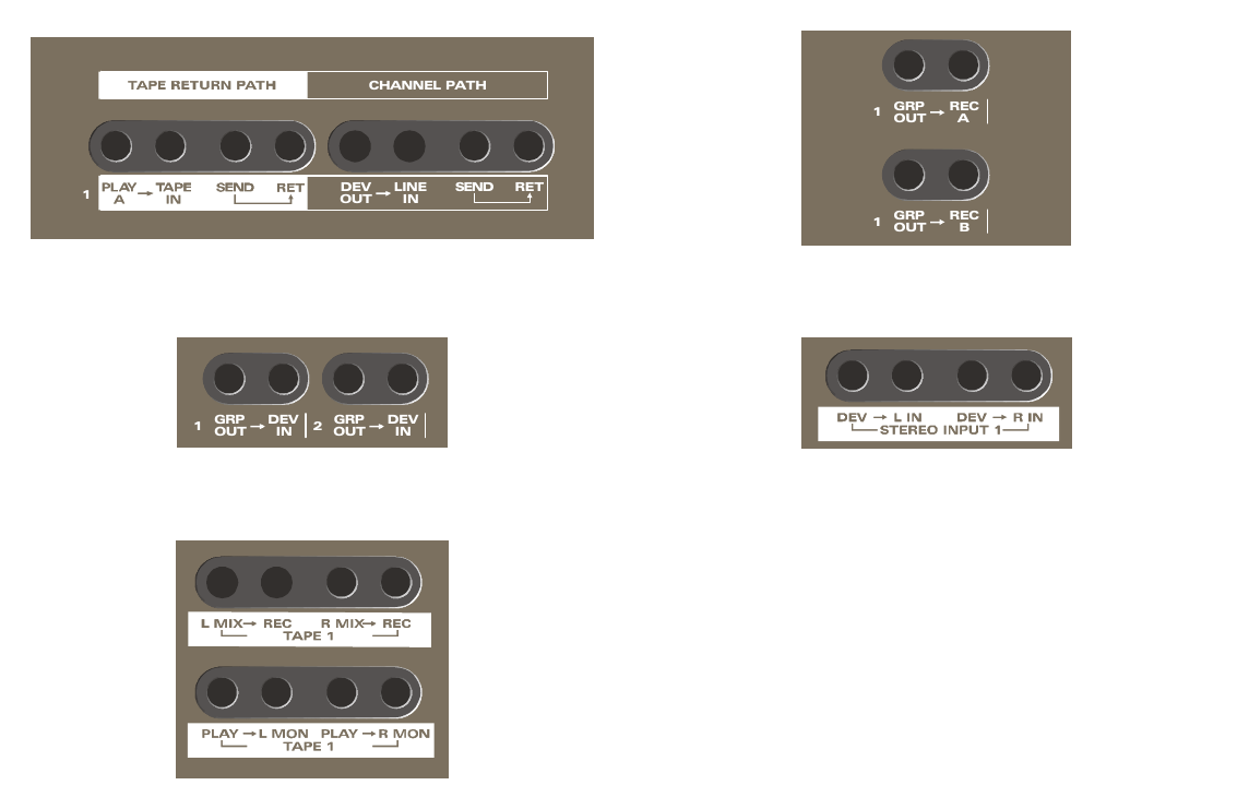
1. Tape return path
Provision is made for two 24-track machines. Tape machine A playback is normalled from the relevant D-sub interface to the Tape inputs of channels 1–24. Tape machine B playback is normalled to channels 25 onwards, up to 48 if this many channels are fitted.
2. Channel path
A rear-panel jack socket is provided for external devices such as synthesizers. This signal is available as Device Output on the patchbay and is normalled to the channel line input.
3. Multitrack sends
Sends to both 24-track machines are normalled from the 24 bus outputs. Machine sends may be overpatched from channel insert sends, subgroups and other points.
4. Stereo inputs
Stereo device outputs such as reverbs are interfaced via 1/4-inch jack sockets on the rear of the console and normalled to the four stereo inputs through the patch jacks.
5. Subgroups
The eight subgroup outputs are normalled to a D-sub connector and may be used to provide outputs to a device such as a non-linear editing system.
6. Stereo tapes
Stereo tape machines are interfaced on rear-panel XLR connectors. Feeds to and from the XLRs are normalled via the patchbay from the Mix output and to the two-track monitor returns respectively.
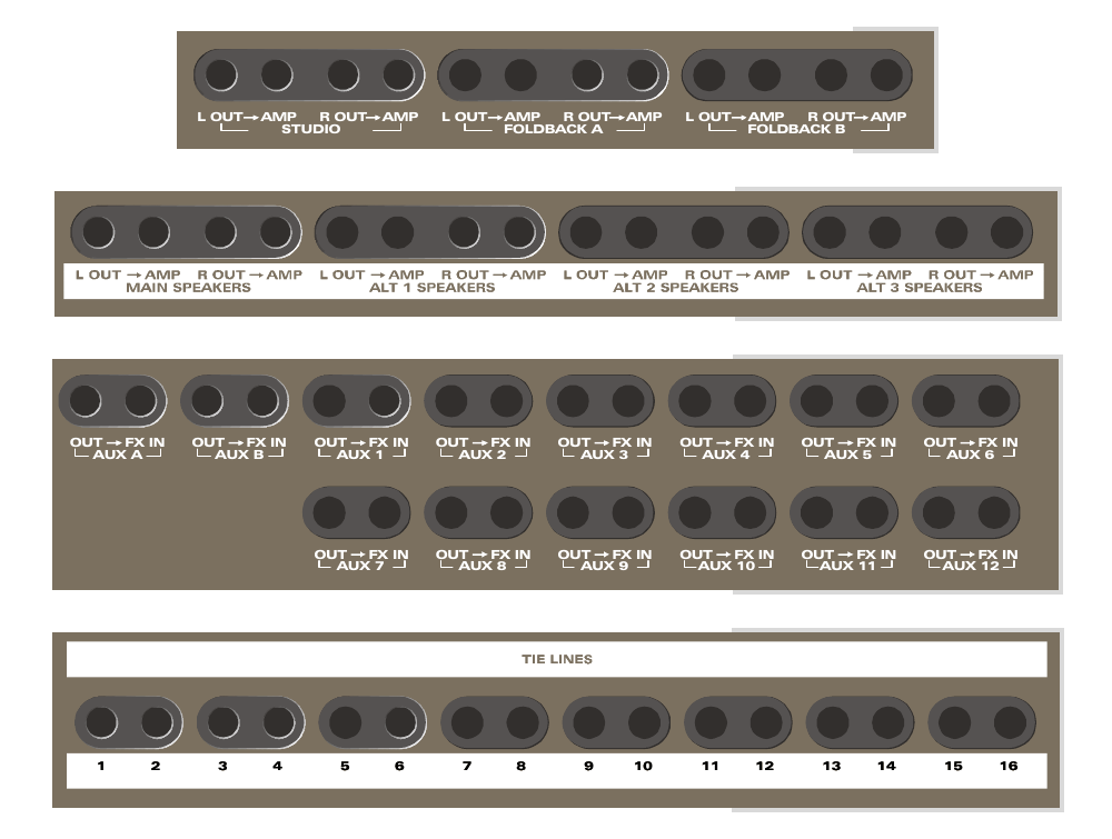
7. Studio/Foldback
Outputs to the foldback and studio-speaker amplifiers are terminated on XLRs on the rear and are normalled from the relevant console sends via the patchbay.
8. Control room
Feeds to the control-monitor speaker amplifiers are normalled via the patchbay to rear-panel XLRs.
9. Auxiliaries
Feeds to external processing devices are normalled from the console auxiliary outputs to rear-mounted XLRs.
10. Tie lines
Tie lines are terminated on D-sub connectors on the rear. Pairs of tie lines may be normalled by fitting two wire links in the positions behind each pair of jacks on the tie-line PCBs.
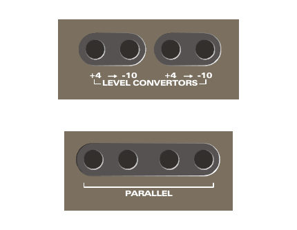
11. Level convertors
Two pairs of passive level convertors are provided. A low-impedance output signal plugged into the +4 dBu jack is attenuated to -10 dBV, suitable for driving inputs of semi-professional equipment.
12. Parallels
Two sets of four-way parallels are provided for paralleling a number of inputs.
Do not use the parallel jacks to join outputs. The original ASP8024 manual warns that doing so will short the outputs together.
Patchbay connector panels
Connections to studio systems on consoles fitted with the ASP8024PB patchbay system are made via rear and bottom connector panels generally in a similar fashion to standard consoles.
Channel connections
Microphone input XLR and Line input jack connectors are located on the rear connector panel behind each input strip as on the standard console. The Tape input and insert send/return jacks are omitted.
Master connections
XLR and jack connectors associated with the master module are arranged in the same way as the standard console, except that subgroup insert send/return jacks are omitted because these are included on the patchbay.
Multitrack record/subgroup connections
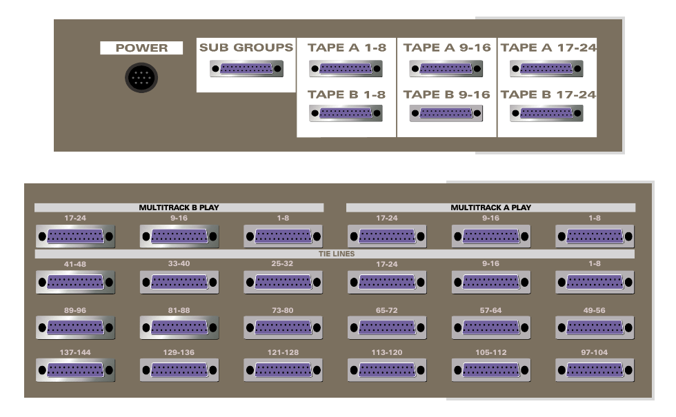
These are on the underside of the console adjacent to the PSU connector. All console interfaces are D-sub female types wired to the Tascam DA88 convention with eight signals per connector.
The source connector-panel drawing shows:
- Power connector
- Sub Groups connector
- Tape A record connectors for channels 1–8, 9–16 and 17–24
- Tape B record connectors for channels 1–8, 9–16 and 17–24
Multitrack play and tie-line connections
These are on the rear panel behind the patchbay section. All connectors are D-sub females wired to the Tascam DA88 convention.
The source connector-panel drawing identifies the multitrack playback connectors as:
| Machine | Playback connector groups |
|---|---|
| Multitrack A | 1–8, 9–16, 17–24 |
| Multitrack B | 1–8, 9–16, 17–24 |
The 144 tie-lines are presented in eight-channel D-sub groups. The rear-panel drawing labels these groups as 1–8 through 137–144.