Master Section Connections
Control room connectors

The control-room loudspeaker outputs comprise a Main output and three Alternative outputs, selected from the control surface. Each output is stereo, with separate left and right connectors.
The console contains no power amplification. Connect passive loudspeakers through suitable external power amplification, or connect self-powered loudspeakers directly to their inputs.
Studio and foldback connectors
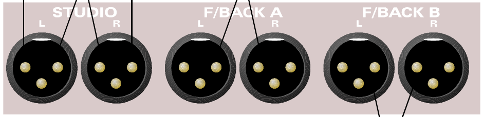
The Studio Loudspeaker, Foldback A and Foldback B outputs are stereo XLR outputs, each with separate left and right connectors. The signal present at each output depends on the source selected on the control surface.
The console does not contain power amplification. Foldback is normally used as a headphone feed; these line-level outputs require suitable external amplification and are not intended to drive headphones or passive loudspeakers directly. Self-powered loudspeakers may be connected directly to their inputs.
Auxiliary connectors
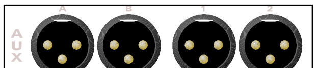
The panel carries XLR connectors for Auxiliary A, Auxiliary B and Auxiliaries 1 through 12. All auxiliaries are mono, line-level, fully balanced outputs. Not all numbered outputs are shown in the source illustration for clarity.
The auxiliary outputs are typically used to feed effects such as reverberation units. Auxiliary A and B are normally used as feeds to the foldback system, but can also be used as additional effects sends.
Subgroup insert connectors
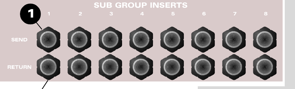
There are eight subgroup insert points. Each subgroup has an INSERT SEND and INSERT RETURN.
Signal is always present on the send output. If required, the insert returns can also be used as very basic inputs to the stereo mix bus during mixdown, for example from a submixer or sampler.
Stereo input connectors
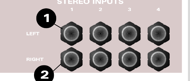
There are four stereo returns, each with left and right TRS jack inputs. If a mono source is used, connect it to the left input. The left input is normalled to the right so the signal feeds both sides of the stereo return. Inserting a plug into the right input breaks this normalled connection.
Play inputs
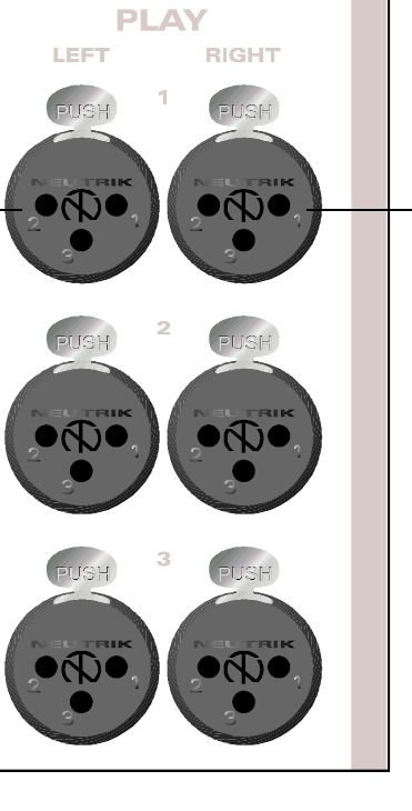
The Play Inputs are external inputs to the monitoring system. All three inputs are available as sources to the Control Room monitoring system. Play 1 and Play 2 can also be selected as sources for the Studio monitoring and Foldback systems.
Each Play input has separate left and right connectors.
Main outputs
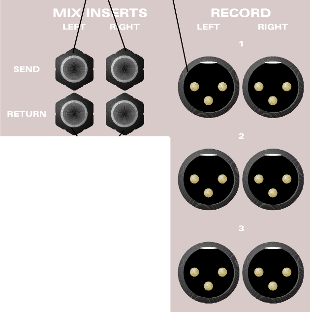
There are three sets of stereo MIX OUTPUT connectors. The source describes these as allowing up to three stereo recording machines to be connected, although the outputs can be used for other destinations as required.
The associated mix insert points allow a final mix processor to be inserted into the MIX path. The insert point is located before the MIX compressor/limiter. Separate left and right MIX INSERT SEND and MIX INSERT RETURN jacks are provided.
Multi-track connectors

The multitrack recorder sends are split across three multi-pole connectors, each carrying eight group outputs:
- Tracks 1–8
- Tracks 9–16
- Tracks 17–24
The eight subgroup outputs are provided on a fourth multi-pole connector. The standard wiring is shown for the D-sub connectors below. Multitrack sends and subgroup outputs were also available as a cost option on 56-pin EDAC multi-pole connectors. Consoles fitted with the optional patchbay do not have the EDAC connector option.
The same panel also carries the console Power Input connector. See Power Supply for the power-supply information retained from the original manual.
Multi-pin connections
| Signal number | +VE D-sub | +VE EDAC | -VE D-sub | -VE EDAC | Screen D-sub | Screen EDAC |
|---|---|---|---|---|---|---|
| 1/9/17 | 24 | A | 12 | E | 25 | F |
| 2/10/18 | 10 | C | 23 | B | 11 | H |
| 3/11/19 | 21 | D | 9 | K | 22 | J |
| 4/12/20 | 7 | P | 20 | V | 8 | N |
| 5/13/21 | 18 | Z | 6 | d | 19 | U |
| 6/14/22 | 4 | c | 17 | f | 5 | Y |
| 7/15/23 | 15 | j | 3 | n | 16 | m |
| 8/16/24 | 1 | t | 14 | y | 2 | s |
All undesignated pins are unconnected. All screen connections are joined inside the console and connected to metalwork earth.
For patchbay-equipped consoles, tie-line connections 25–32 and subsequent groups follow the same wiring convention. Patchbay-equipped consoles do not have the optional EDAC connectors.