Block Diagrams
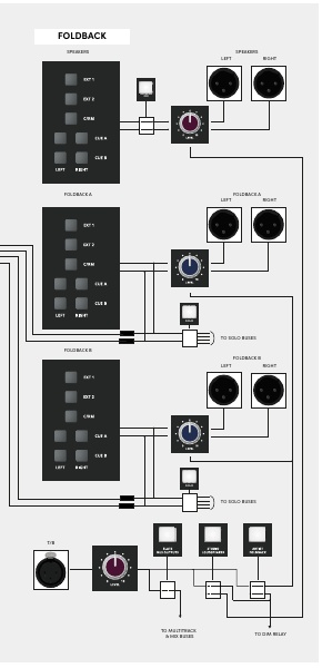
The following diagrams show the principal ASP4816-SE signal paths and routing relationships.
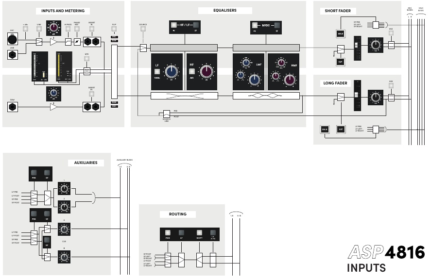
Channel input signal flow
Aux and Cue master signal flow
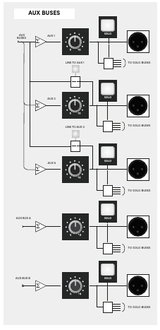
The source diagram shows the Aux 1/3/5 side of the linking architecture. Aux 2/4/6 operate in the corresponding mirrored arrangement, with Aux 4 and Aux 6 linking to Aux 2.
Oscillator signal flow

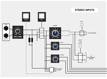
Stereo Input signal flow
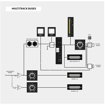
Record Bus and Subgroup signal flow
Studio and Foldback signal flow
Mix-bus processing order
The detailed control sections establish the following order around the stereo Mix processing:
Stereo Mix bus → Mix Insert → onboard VCA bus compressor → Master Fader / Mix outputs
Integration Port signal map
| Channel | Function |
|---|---|
| 1 | Control Room Output Left |
| 2 | Control Room Output Right |
| 3 | Guide Track Output Left |
| 4 | Guide Track Output Right |
| 5 | Remote DIM DC |
| 6 | Remote SOLO DC |
| 7 | Not used |
| 8 | Not used |