Rear-Panel Connectors
Control Room outputs
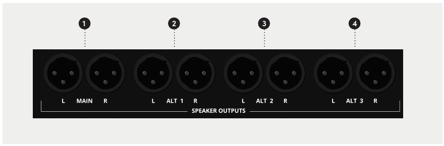
ASP4816-SE provides four stereo control-room monitor outputs: Main, Alt 1, Alt 2 and Alt 3, each on separate left and right XLR connectors. These are line-level outputs and must feed active monitors or a suitable loudspeaker power amplifier.
Studio and Foldback outputs
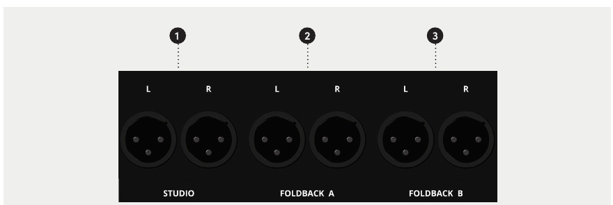
The Studio, Foldback A and Foldback B outputs are stereo line-level XLR pairs. Connect the Studio output to active monitors or a suitable loudspeaker amplifier, and Foldback outputs to an appropriate headphone amplifier/distribution system.
Aux and Cue outputs
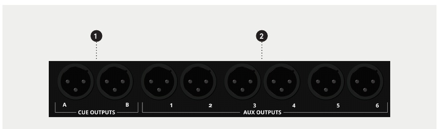
ASP4816-SE provides Cue A, Cue B and Aux 1–6 as balanced line-level XLR outputs. Cue A/B are normally used for foldback but may also be used as additional effects sends.
Subgroup Insert / Line Input 17–24
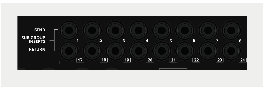
Each subgroup provides an Insert Send and Insert Return. Signal is always present at the Insert Send. The eight Insert Returns can alternatively be used as Line Inputs 17–24:
Subgroup 1 → Line 17 through to Subgroup 8 → Line 24.
The same return socket cannot be used simultaneously as a subgroup insert return and additional line input.
Stereo Input connectors
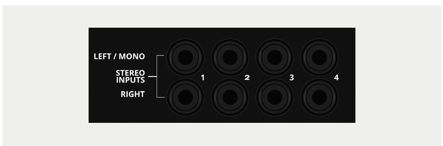
Each of the four Stereo Inputs has LEFT / MONO and RIGHT TRS inputs. For a mono source, connect to LEFT / MONO only; with nothing connected to RIGHT, the Left signal is normalled to both return paths. Connecting a plug to RIGHT breaks this normal.
Monitor inputs
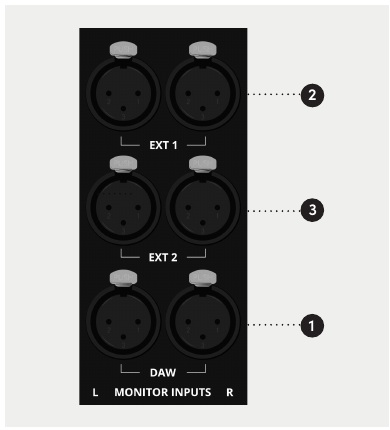
The Control Room can monitor DAW, EXT 1 and EXT 2 rear-panel stereo inputs. EXT 1 and EXT 2 are also available as external sources in the Studio/Foldback section.
Mix Insert and Mix outputs
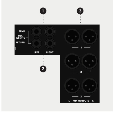
Separate left/right Send and Return connections provide the stereo Mix Insert. The Mix Insert is positioned before the onboard VCA bus compressor.
Three stereo Mix output pairs carry the same stereo Mix signal and may all be used simultaneously.
Record Bus / Subgroup outputs
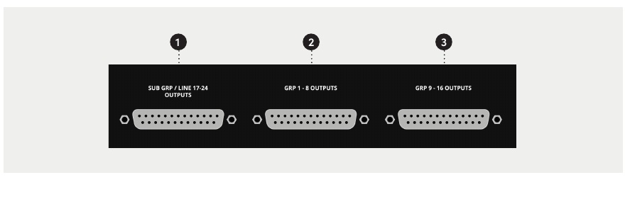
The 16 record-bus outputs are divided across two DB25 connectors: buses 1–8 and buses 9–16. The Subgroup / Line 17–24 outputs use a third DB25 connector. All use the Tascam-standard analogue pinout.
Integration Port

| DB25 channel | Function |
|---|---|
| 1 | Control Room Output Left |
| 2 | Control Room Output Right |
| 3 | Guide Track Output Left |
| 4 | Guide Track Output Right |
| 5 | Remote DIM — approximately 12 V DC when active |
| 6 | Remote SOLO — approximately 12 V DC when active |
| 7 | Not used |
| 8 | Not used |
The stereo Guide Track is derived from Aux 5 and Aux 6.
The Integration Port is not an eight-channel audio output. Channels 5 and 6 carry DC control signals for Remote DIM and Remote SOLO.