Console Layout, Architecture and Metering
Console layout
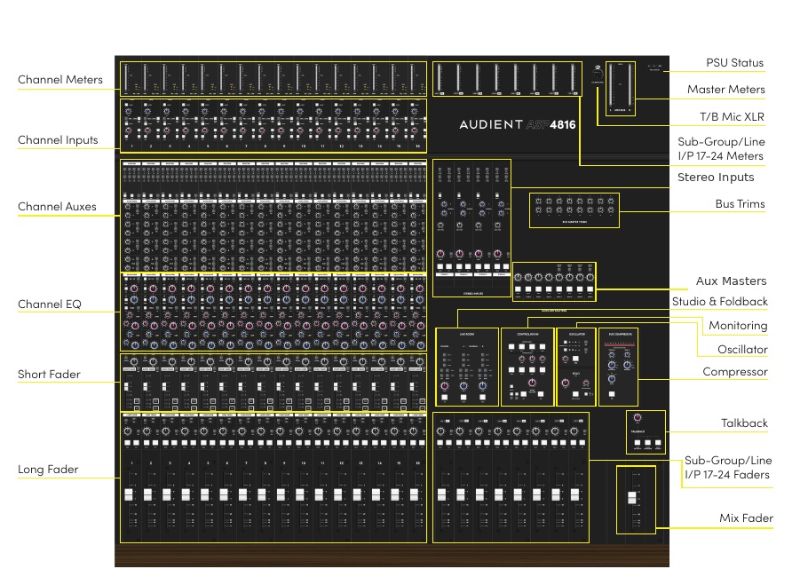
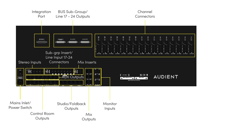
In-line architecture
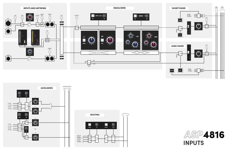
ASP4816-SE contains two signal paths within each physical channel strip:
- SF — Short Fader path
- LF — Long Fader path
On ASP4816-SE, light control-surface areas and light path-selection switches are associated with the SF path, while darker areas are associated with the LF path.
Default source assignment
| FLIP | SF path | LF path |
|---|---|---|
| Released / normal | Mic/Line | DAW |
| Pressed | DAW | Mic/Line |
The FLIP switch swaps the Mic/Line and DAW sources between the two paths. Backlit source indicators show the active source for each path.
Path assignment
The HF/LF and MIDS EQ sections can each be moved from the LF path to the SF path using their SF switches. Aux 1–6 can also be sourced from LF or SF in three pairs, while Cue A and Cue B can be switched individually. The routing matrix normally receives the SF path and can be switched to the LF path using LF in the routing section.
When tracking in the normal configuration, placing an EQ section in the SF path applies that EQ to the normal record path. EQ in the LF path affects the monitored/mix path. If the LF path itself is subsequently routed to a record bus or recorded from the stereo Mix output, LF-path EQ will be included in that routed signal.
Metering
By default, the 20-segment channel meter displays the DAW input and the 3-segment meter displays the Mic/Line input. Press MTR to swap the two meter sources.
ASP4816-SE meters are peak-reading and use a dBu scale.
- 0 VU = +4 dBu
- +18 dBu = 0 dBFS when the connected converter is aligned so that +18 dBu corresponds to digital full scale
- With this converter alignment, 0 VU corresponds to approximately −14 dBFS, providing 14 dB of digital headroom
The console itself can pass analogue signal levels above +18 dBu; +18 dBu is a digital alignment reference rather than the console's maximum analogue level.
Meters are provided for:
- Main Stereo Output — 30 segments
- Line Inputs 17–24 / Subgroup Outputs — 20 segments
- DAW Inputs — 20 segments
- Mic/Line Inputs — 3 segments
Typical hybrid signal flow
A typical setup is:
Microphones / line sources → ASP4816-SE → record-bus outputs → A/D conversion / audio interface → DAW → D/A conversion / audio interface → ASP4816-SE DAW inputs
Channel inserts can feed external processing, the Control Room outputs feed the monitor system, and the Foldback outputs normally feed an external headphone amplifier or distribution system.