Compressor and Heritage Mix Processing
Stereo mix-bus compressor
The compressor sits in the main stereo path after the Mix Insert and before the Master Fader.
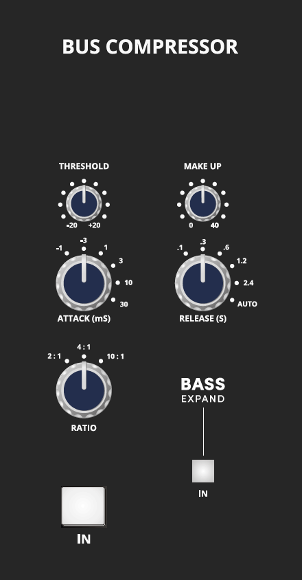
The compressor provides:
- Threshold: -20 dBu to +20 dBu.
- Attack: six steps from 0.1 ms to 30 ms.
- Ratio: 2:1, 4:1 or 10:1.
- Makeup gain: up to 40 dB.
- Release: five steps from 0.1 s to 2.4 s, plus Auto.
- IN: switches the compressor into circuit.
- BASS EXPAND: inserts a 350 Hz high-pass filter in the sidechain, reducing the extent to which low-frequency energy triggers compression.
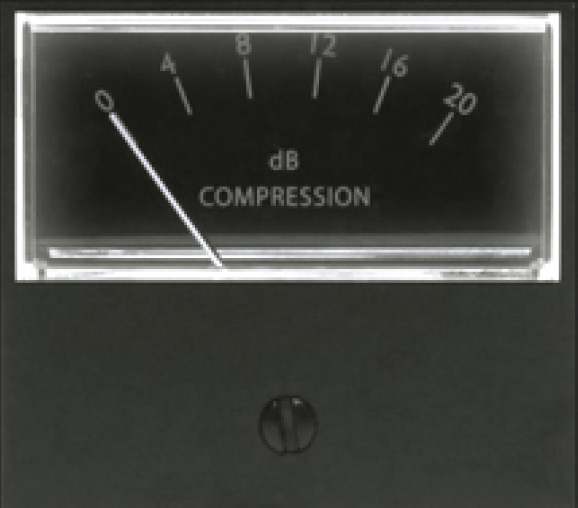
The analogue gain-reduction meter shows the amount of gain reduction being applied.
For general mix-bus use, small amounts of gain reduction may be sufficient. A higher threshold with a higher ratio can also be used to control peak signals so the compressor acts primarily when the threshold is exceeded.
Heritage mix-bus processing
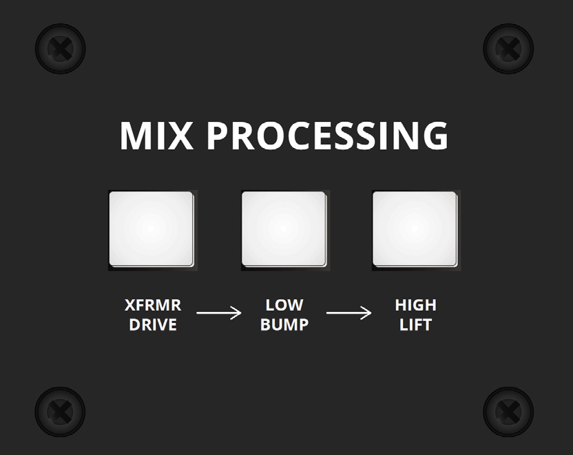
XFRMR Drive
XFRMR DRIVE introduces two Carnhill output transformers into the signal path. A useful workflow is to engage XFRMR Drive during a mix and then balance the mix with the transformer stage active.
Low Bump
LOW BUMP applies a broad low-frequency lift centred around 60 Hz.
High Lift
HIGH LIFT applies a broad high-frequency lift around 20 kHz.
Low Bump and High Lift are part of the transformer processing circuit and only affect the Mix while XFRMR Drive is engaged.
John Hardy 990C+ mix-bus op-amps
The mix-bus summing circuit uses a pair of discrete John Hardy 990C+ op-amps. The manual describes the discrete summing stage as providing a very low noise floor and fast transient response.
Main Mix signal order
The console block diagram confirms the main Mix signal flow as:
Mix buses → SIP relay → Heritage bus processing → Mix inserts → compressor → Master Fader → Mix outputs.
Continue to Stereo Inputs, Subgroups and Masters.