Console Architecture
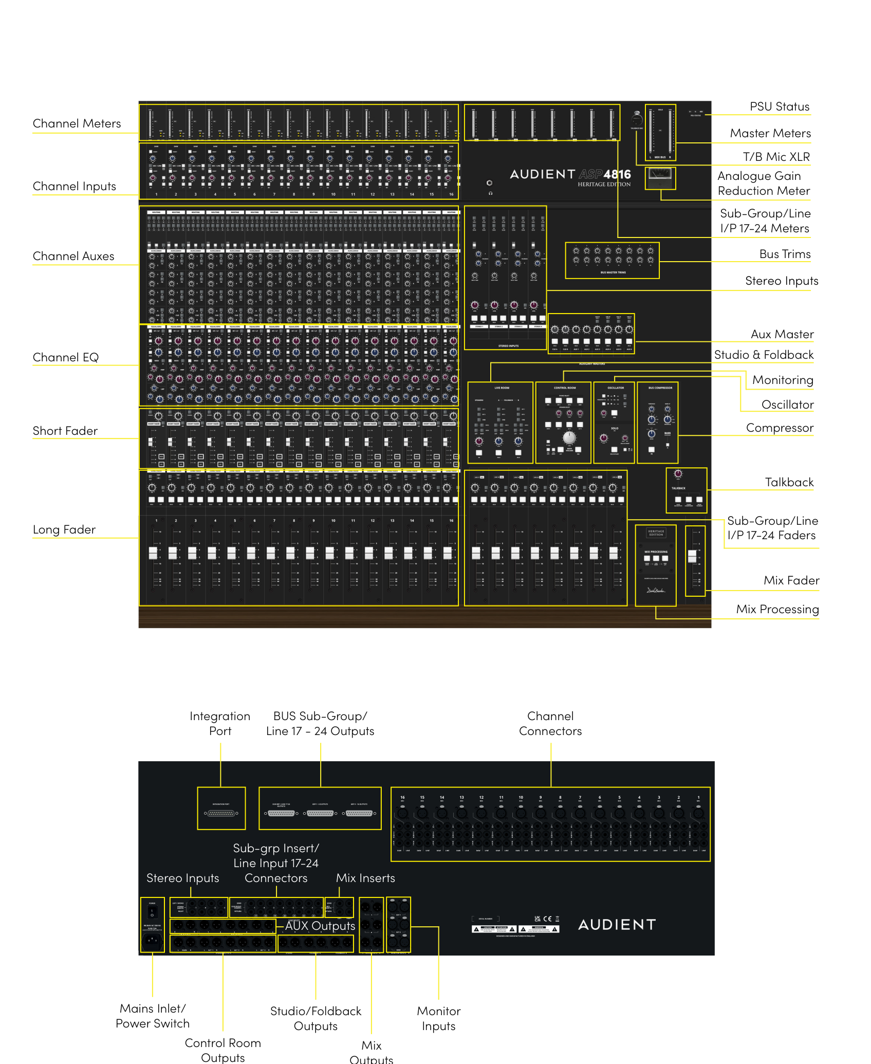
Console layout
The layout below identifies the main control-surface sections and rear-panel connection groups.
In-line architecture
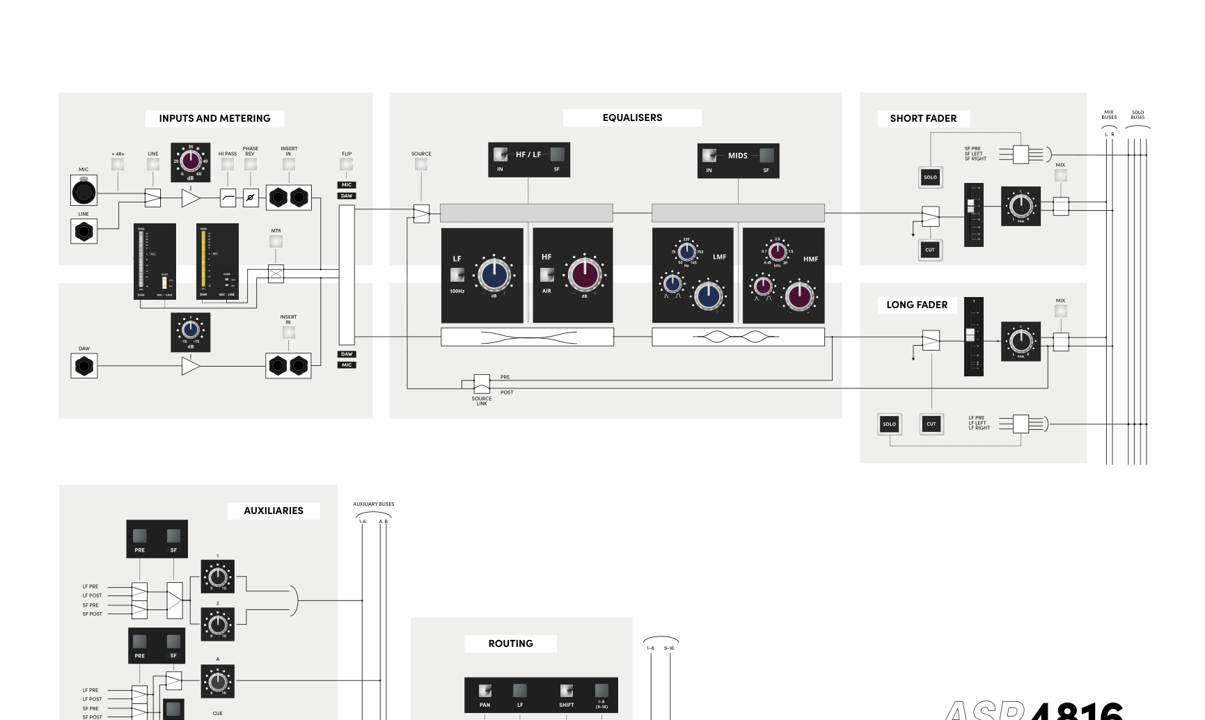
Each ASP4816-HE input strip contains two independent signal paths in the same physical channel strip:
- SF (Short Fader) — normally the Mic/Line recording path.
- LF (Long Fader) — normally the DAW return and monitoring/mix path.
With FLIP disengaged:
- Mic/Line → SF
- DAW → LF
With FLIP engaged:
- Mic/Line → LF
- DAW → SF
Backlit MIC/DAW legends indicate the input currently assigned to each path.
Sharing EQ between paths
The HF/LF EQ section and the MID EQ section each have an SF switch.
- With the SF switch disengaged, that EQ section is in the LF path.
- With the SF switch engaged, that EQ section is moved to the SF path.
The two EQ sections can therefore both be in LF, both be in SF, or be split between the paths.
When EQ is moved to the SF recording path, its effect can be recorded. When the EQ remains in the LF monitoring path, it affects what is heard through that path without altering the Mic/Line recording path.
Sharing auxiliary sends
Auxiliary pairs can also be switched between LF and SF. Each pair can operate pre- or post-fader for the selected path.
Typical system configuration
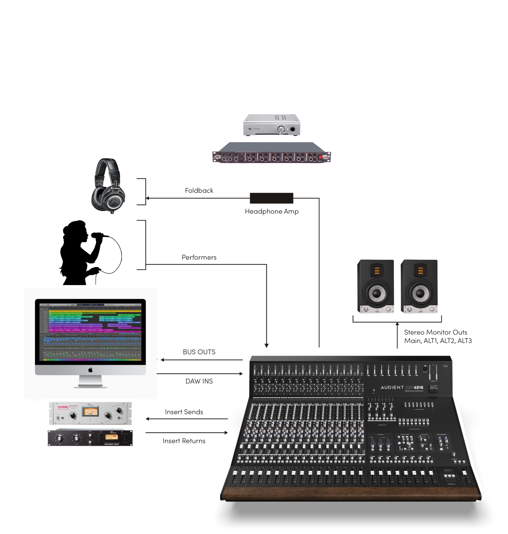
The console can sit between performers, a DAW, outboard processing, foldback/headphone amplification and multiple monitor pairs. Bus outputs feed the recording system, DAW returns feed the console, and insert sends/returns provide series outboard processing.
Continue to Metering and Solo.