ASP4816-HE Manual
ASP4816-HE is a compact in-line analogue recording console designed for tracking, mixing, signal routing, analogue summing and studio monitoring. It combines 40 faders and 48 inputs at mix with 16 Audient Class-A discrete microphone preamps, two signal paths per input strip, 16 record buses, eight subgroups, six numbered auxiliaries, two cue buses, four stereo monitor outputs, a stereo VCA mix-bus compressor and Heritage Edition mix-bus processing.
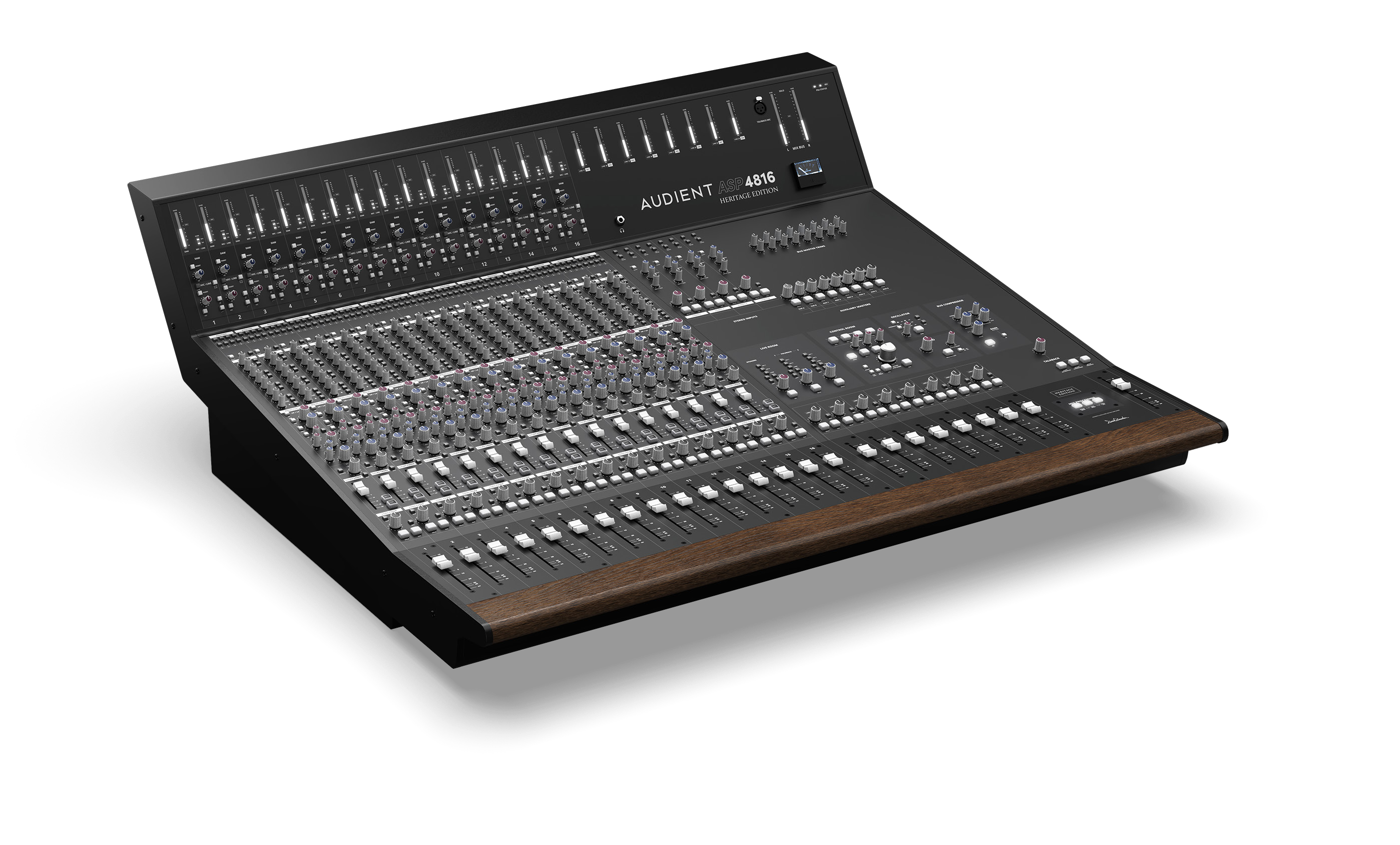
Principal features
- 16 Class-A discrete Audient microphone preamps.
- In-line channel architecture with separate Short Fader (SF) and Long Fader (LF) paths.
- 16 bus outputs, with buses 1–8 also feeding eight subgroups.
- Six numbered auxiliary sends plus Cue A and Cue B.
- Four-band EQ with independently assignable HF/LF and mid sections.
- Four stereo inputs for additional returns during mixdown.
- Four stereo control-room monitor outputs: Main, ALT 1, ALT 2 and ALT 3.
- Stereo VCA mix-bus compressor with analogue gain-reduction meter and Bass Expand sidechain filter.
- Heritage Edition XFRMR Drive, Low Bump and High Lift processing.
- John Hardy 990C+ discrete op-amps in the mix-bus summing circuit.
- Dedicated Studio, Foldback, Talkback and Integration Port facilities.
Recording workflow
The manual frames recording around three broad stages: tracking, editing and mixing. During tracking, live sources are captured through the Mic/Line and SF paths. During editing, the console monitoring section can be used to audition and manage DAW playback. During mixing, recorded DAW tracks return to the LF paths and are combined through the analogue Mix bus.
How the console is organised
The ASP4816-HE uses an in-line architecture. In its normal state the Mic/Line input feeds the SF path and the DAW input feeds the LF path. Pressing FLIP reverses these assignments. EQ and auxiliary sections can be moved between paths, allowing the same physical strip to handle a recording path and a monitoring/mix path at the same time.
The light areas of the channel strip are associated with the SF/channel path. The darker areas are associated with the LF/monitoring path.
Manual sections
Start with Installation and Safety, then use the hardware, routing and workflow pages as required. For the complete signal-flow drawings, see Block Diagrams and Signal Flow.
Continue to Installation and Safety.