Block Diagrams and Signal Flow
Input channel block diagram
The input-channel diagram shows Mic, Line and DAW inputs, input metering, inserts, FLIP, EQ assignment, LF/SF faders, auxiliary sourcing and bus routing.
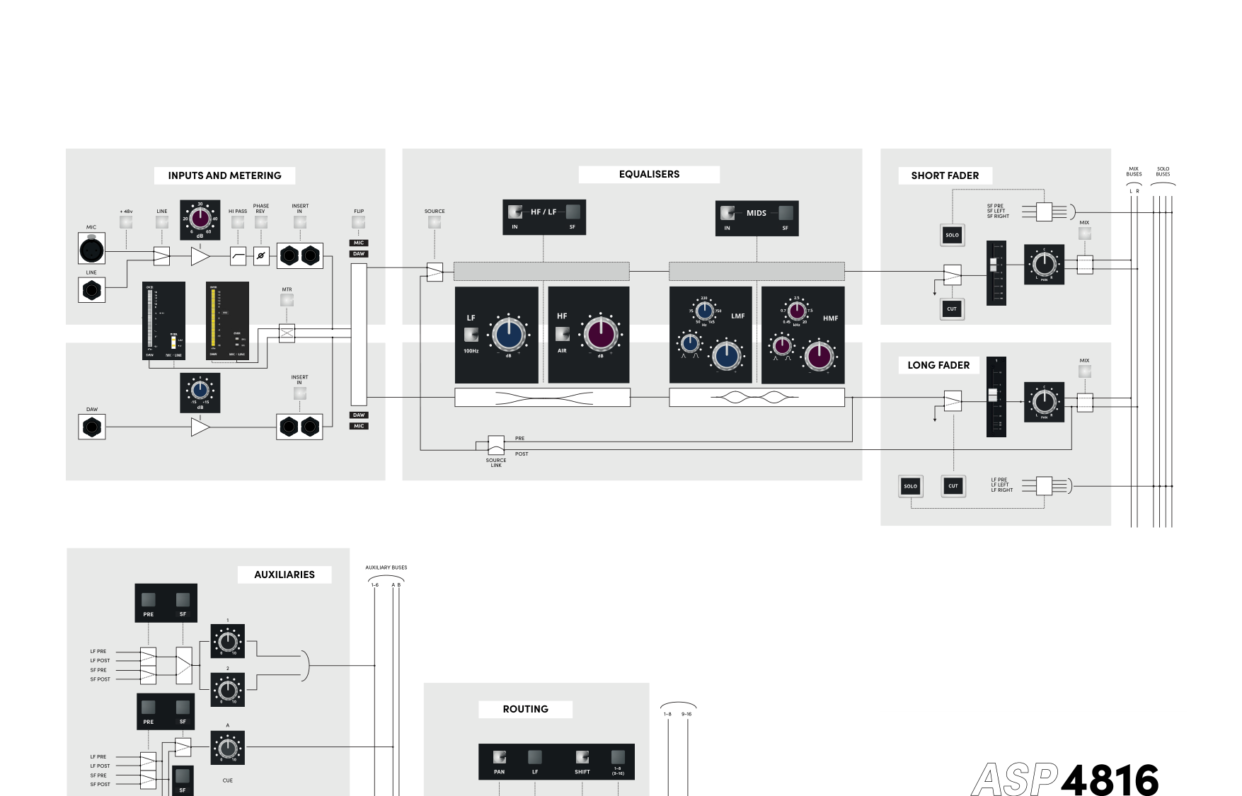
Key relationships shown by the diagram include:
- Mic/Line and DAW metering occur before FLIP.
- FLIP swaps the source assignments between LF and SF.
- HF/LF and MID EQ sections can be moved independently between paths.
- Auxiliary sends can select LF or SF and pre/post-fader sources.
- Routing can select SF or LF before the bus-routing controls.
Master section — Part 1
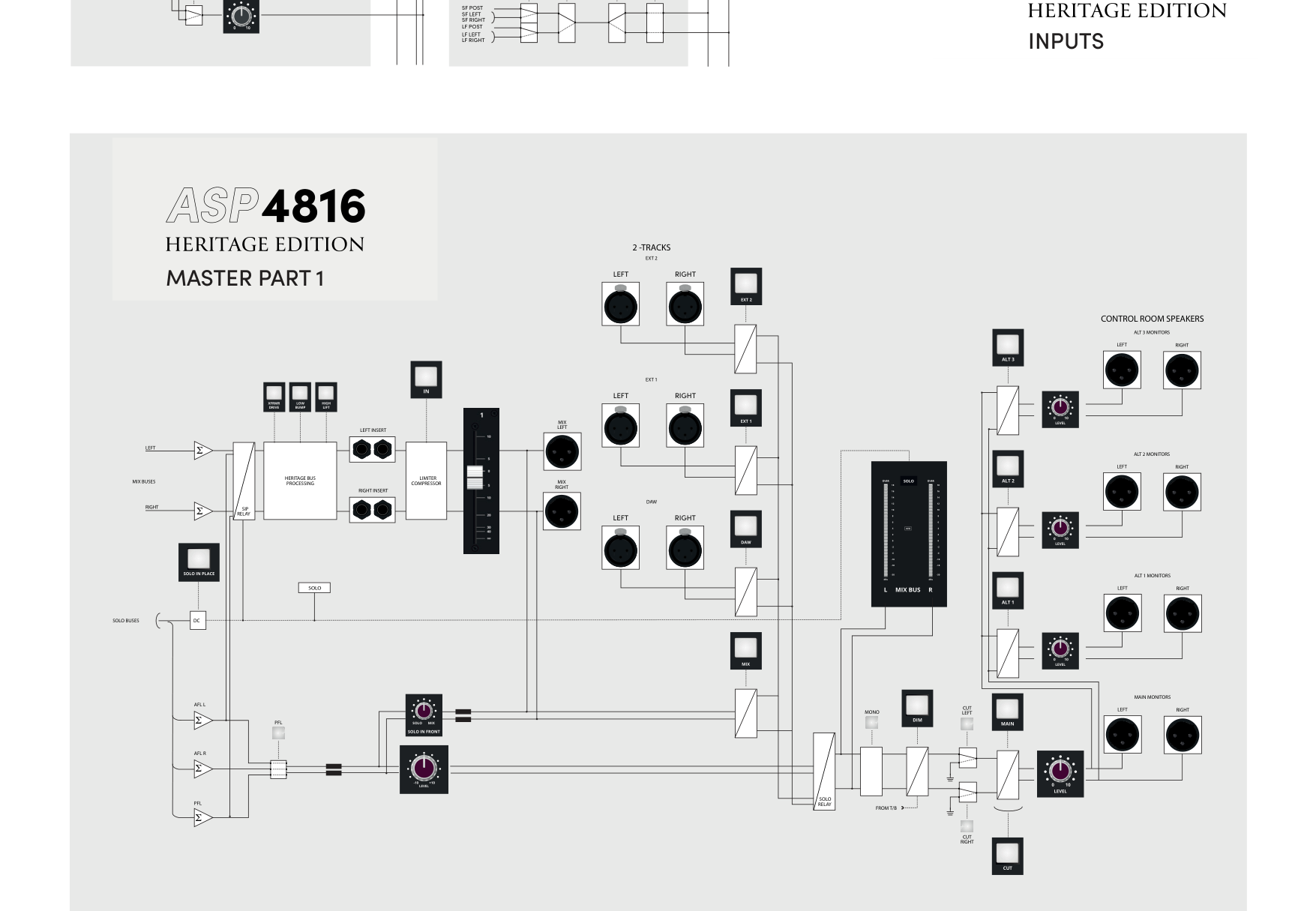
The master diagram confirms this Mix-bus order:
Stereo Mix buses → SIP relay → Heritage processing → Mix Insert → compressor → Master Fader → Mix outputs.
It also shows the Solo and control-room monitoring paths, including source selection, Mono, Dim, Left/Right Cut and the Main/ALT monitor outputs.
Master section — Part 2
The second master diagram covers the auxiliary buses, Stereo Inputs, multitrack/subgroup buses, oscillator, Studio/Foldback and Talkback paths.
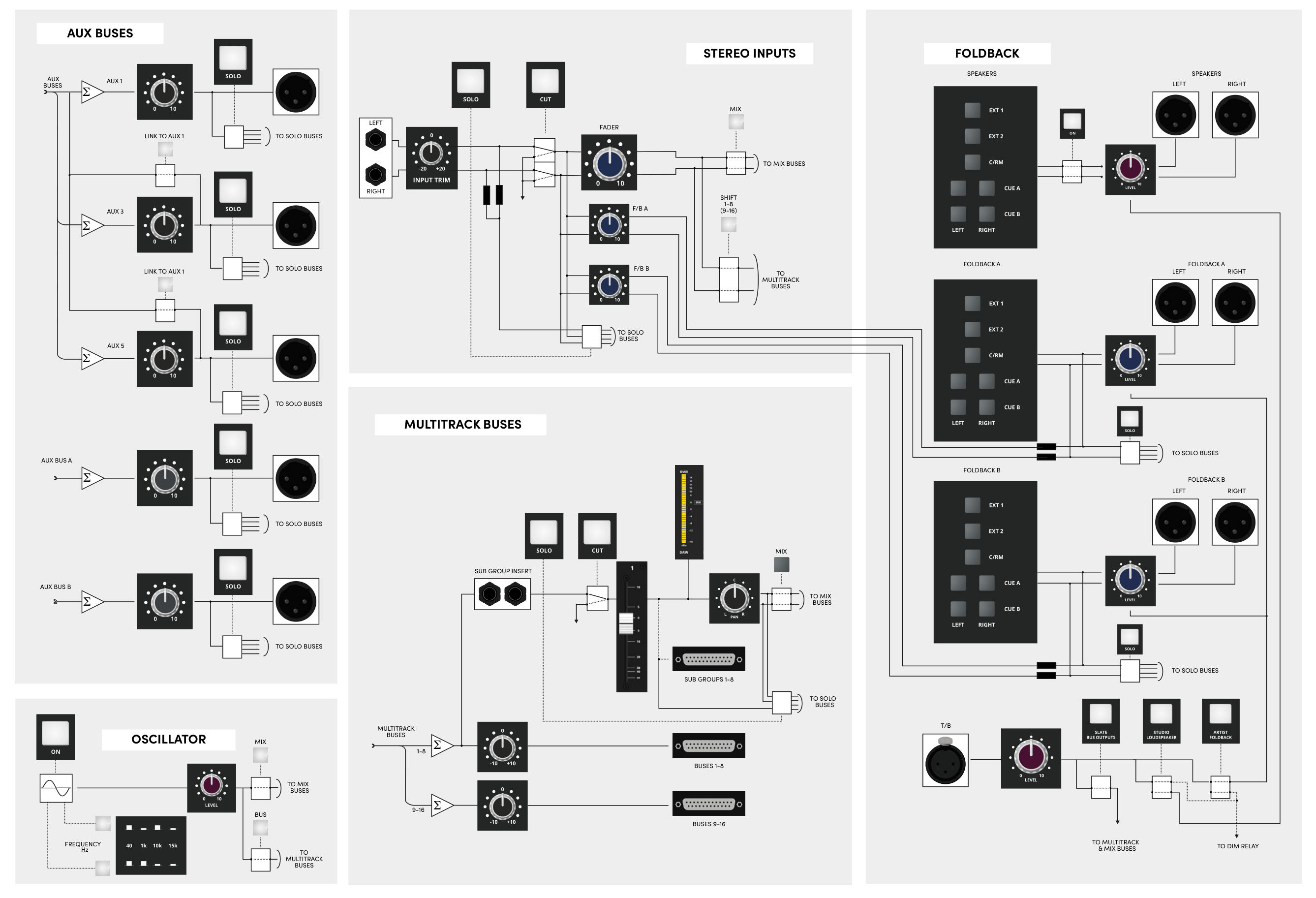
Aux, subgroup, oscillator and foldback relationships
The remaining master architecture provides:
- Aux 3 and 5 linking to Aux 1.
- Aux 4 and 6 linking to Aux 2.
- Stereo Input routing to Mix, recording buses and Foldback.
- Buses 1–8 feeding the subgroup section.
- Oscillator routing to buses 1–16 or the stereo Mix.
- Studio/Foldback source selection from external inputs, Control Room and Cue A/B.
- Talkback routing to Slate Bus Outputs, Studio Loudspeakers and Artist Foldback, with Control Room Dim activation.
Use the routing, master and monitoring pages alongside these diagrams for the detailed control descriptions.
Continue to Technical Specifications.